

Cap Mould Manufacturer | Custom Plastic Bottle Cap Molds

Why choose Go4mould for your bottle cap mould?
Cap molds play a critical role in the packaging industry. From beverage bottles to pharmaceutical containers, accurate closures ensure product safety, freshness, and brand integrity. At Go4mould, we manufacture high-performance cap molds engineered for durability, speed, and long-term production performance.
- 25+ years of expertise in bottle cap mould manufacturing for global markets
- 8 to 64 cavity options to match your production volume and cost targets
- Lifetime maintenance guarantee on all cap mold orders
- Hot runner systems for consistent quality and reduced material waste
- Precision tolerance of ±0.01mm across all bottle cap mould designs
- Full customization — material, cavity number, gate type, and surface finish
We serve clients across the beverage, pharmaceutical, cosmetic, and food industries, delivering cap molds that combine durability, efficiency, and competitive pricing.
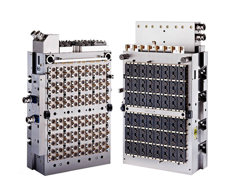
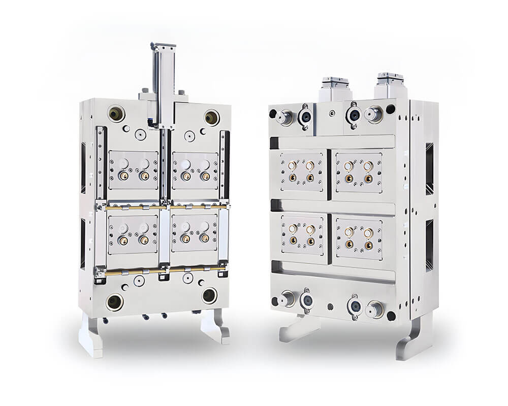
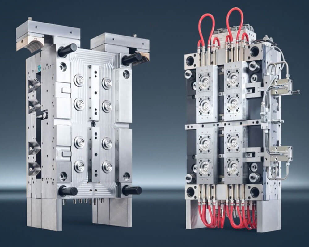
Our bottle cap mould product range
Go4mould manufactures a complete range of plastic bottle cap moulds to suit diverse industry needs. Each cap mold is engineered with high-grade steel and optimized for high-speed, high-volume production.

Our screw cap mold is widely used for oil bottles, beverage bottles, and household product containers. Available in multiple cavity configurations, this bottle cap mould delivers consistent thread precision and fast cycle times.

Designed for large drinking water buckets, our 5 gallon bottle cap mold features a complex internal structure with superior sealing performance. Built with S136 steel and a hardness of 45–52 HRC, this cap mould is engineered for long service life.
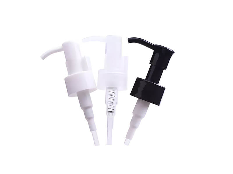
Available in a wide variety of styles and structures, our shampoo cap mould can be fully customized to your design drawings or product samples. We support both injection and compression cap mold processes for this product type.
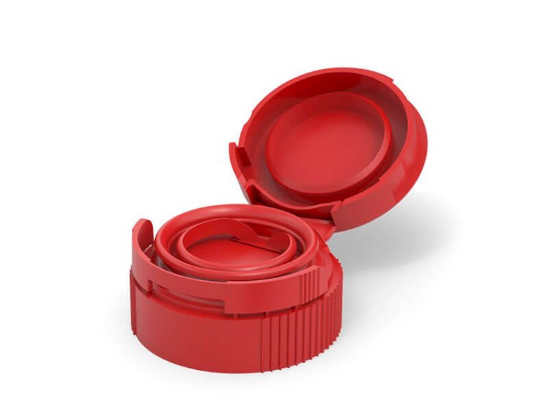
The flip top cap mold is one of our flagship products. With cavity options ranging from 8 to 64, this cap mould is ideal for shampoo, conditioner, sauce, and personal care packaging lines that require high daily output.
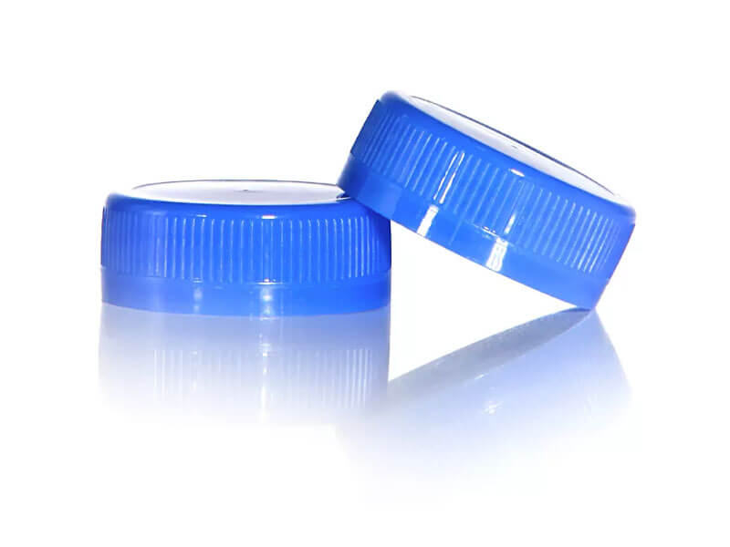
This is the most widely produced plastic cap mold globally. Go4mould offers mineral water cap moulds in various cavity configurations to match different production scales, with compatibility with PP and HDPE.
Go4mould: Your trusted cap mold manufacturer in China
Sourcing a reliable bottle cap mould manufacturer requires more than just a low price. It demands proven technical capability, consistent quality, and dependable after-sales support. Go4mould has built its reputation over 25 years by delivering exactly that.
Our facility in Taizhou, China — one of the world’s leading mold manufacturing hubs — is equipped with CNC machining centers, EDM spark machines, high-precision grinders, and full 3D measurement systems. Every cap mold we produce goes through rigorous T1 sample trials and dimensional verification before shipment.
We work with clients at every stage of the product lifecycle — from initial cap mold design and Moldflow simulation, through to mass production tooling and long-term mold maintenance. Whether you are placing your first bottle cap mould order or scaling up an existing production line, Go4mould has the expertise and capacity to deliver.
Contact us today to discuss your cap mold requirements and receive a detailed quote within 24 hours.
We care about every aspect of your cap mold needs
- Factory view
- Technical specifications

Go4mould’s cap mold manufacturing capabilities cover a wide range of materials, structures, and production requirements. Below are the standard technical parameters for our bottle cap moulds:
| Parameter | Specification |
|---|---|
| Mould base | LKM, HASCO, SD Standard |
| Mould Material | S136, 718H, NAK80, M238, P20, etc. |
| Moud Precision | ±0.01mm |
| Mould Life | 50-500K shots |
| Mould Cavity | 8-cavity, 16-cavity, 24-cavity, 32-cavity, 48-cavity, 64-cavity |
| Runner System | Hot runner system and the temperature control system |
| GateType | Valve gate, pin-point gate, sub gate |
| Cap Material | PP, HDPE, LDPE, PET, PE |
| Surface Treatment | Polishing, texturing, and chrome plating |


Send Inquiry

Cap Mould Selection Guide: Plastic Injection Cap Mold Types, Materials, and Sourcing
The wrong cap mould decision doesn’t announce itself — it shows up later in scrap bins and missed delivery windows. Whether you are sourcing a plastic injection cap mould for a new beverage line or re-evaluating an underperforming bottle cap mold, the tool you commission sets the ceiling on output and the floor on scrap. Cap closures are contact-critical components: they determine seal integrity, tamper evidence, and consumer safety across food, beverage, medical, and industrial packaging, and the mould producing them carries that responsibility at every shot. Most sourcing mistakes trace back to one overlooked variable — how the mould handles thread release under high-cavitation, high-speed conditions. This guide gives you the classification framework, material and steel logic, and selection criteria to brief a cap mould manufacturer with confidence and get the decision right the first time.
What Is a Plastic Cap Mould?
A cap mould is a precision injection mould engineered specifically to produce plastic closures — bottle caps, screw caps, flip-tops, and tamper-evident rings. Whether your team writes it as cap mould (British spelling) or cap mold (American spelling), the term refers to the same hardened-steel injection tool that shapes molten plastic into finished bottle caps — not to glass, resin, or architectural moulding. Its job is to replicate a defined closure geometry — internal threads, sealing lips, and locking features — with dimensional consistency across millions of cycles. A standard injection mould makes a part and ejects it; a cap mould does the same under far tighter tolerances. A thread pitch deviation of 0.05 mm can cross-thread a cap or fail a torque test on the filling line, and the mould must hold that precision at cycle times often under five seconds.
Threads, tamper bands, and sealing beads are formed directly in the cavity during injection, not machined afterward. Internal threads are created by threaded cores, and the cap leaves the core by unscrewing, collapsing, or stripping. Tamper-evident bands connect to the cap body through frangible bridges formed by thin steel inserts; venting around those inserts is critical, because trapped air causes short shots and incomplete bridges. Specialized closures — sports caps, child-resistant tops, dispensing valves — add geometry that demands side cores, lifters, or split cavities.
Four pressures separate cap moulding from general injection moulding:
- Cycle speed — beverage cap moulds run at four to six seconds, so cooling is the primary constraint on cycle time, not a supporting function.
- Venting — shallow, wide cavities must clear air from the thread roots and the sealing surface at the same time, or burn marks fail leak testing.
- Thread release — the disengagement mechanism drives cycle time, quality, and complexity; picking the wrong one for a given thread geometry is the most common and costly error in cap mould procurement.
- Runner configuration — high-cavitation beverage tools almost always gate through hot runners.
A cap mould is always an injection mould — blow moulding inflates a parison to form bottles and cannot achieve closure geometry.
The assembly is straightforward to brief. The core forms the inside of the cap (internal threads and sealing surface); the cavity forms the outside and the parting-line cut-off. Stripper rings spread ejection force evenly around thin rims to prevent distortion, and a balanced hot-runner manifold feeds every cavity at equal rate and pressure. Ejection choice is not interchangeable: stripper-ring ejection protects circularity, while pin ejection risks witness marks; premature ejection while the part is still hot produces ovality and inconsistent removal torque. The first mass-produced closure — the 1892 crown cork — needed only crimping; threaded plastic closures arrived in the 1960s and forced helical thread geometry, undercut demolding, and tighter tolerances, and tamper bands, child-resistant tops, and dispensing features followed. That trajectory is why precision injection tooling, not stamping or casting, is the modern standard for the roughly USD 3.9 billion global bottle-cap market.
Types of Plastic Cap Moulds and Thread Demolding
Cap mould type follows from thread geometry, material flexibility, cavity count, and production volume — each factor pulling toward a different mechanism.
- Compression moulds feed a measured charge (typically HDPE or PP) into an open cavity with no runner or gate. They suit simple, shallow caps at high speed with minimal waste, but cannot form complex internal geometry, undercuts, or flip-top hinges.
- Injection moulds dominate cap production, forming threads, sealing lips, tamper bands, and walls in a single shot across 16, 32, 48, or more cavities. They are the right choice for living hinges, dispensing valves, child-resistant features, and insert moulding.
- Unscrewing moulds rotate the threaded core in sync with ejection — driven by hydraulic motors (high torque, slower), rack-and-pinion (mechanical, cost-effective for moderate depths), or servo motors (programmable, best for synchronized high-cavitation tools). They are required for deep threads, sharp flanks, or multi-start threads; trying to strip a sharp-flanked PP thread fails at the root.
- Forced-stripping (push-off) moulds push the cap off a stationary core, relying on material flex and a stripper ring or plate. Mechanically simple and fast, but limited to shallow, rounded threads — too sharp or deep and the thread profile permanently distorts.
- Collapsible-core moulds collapse segmented core elements inward to release internal undercuts, balancing thread integrity against cycle time, at the cost of segment-edge wear over time.
- Stack moulds place cavities on two levels around a central manifold to double output within the same press footprint — justified when clamp force is available and volume amortizes the higher tool cost.
- Custom and specialty moulds handle child-resistant, push-pull, and multi-component closures with side actions, lifters, inserts, and staged ejection. They are specification-driven, worked backward from torque windows, leak tests, and hinge cycle-life targets.
Plastic Materials for Cap Production
Resin choice drives cap performance and dictates cooling time, gate location, and demolding mechanism, so confirm it before tooling begins. The four workhorse resins each carry a distinct shrink rate that the cavity must be cut to compensate for:
- Polypropylene (PP) is the dominant cap resin — chemical resistance, low density, good hinge flex for flip-tops, and a low melting point that speeds cycles. It is the default choice for most bottle cap injection molding programmes. Shrinks roughly 1.5–2.0%.
- High-Density Polyethylene (HDPE) adds rigidity and impact resistance for heavy-duty and tamper-evident closures but needs longer cooling. Shrinks roughly 2.0–3.0%.
- Low-Density Polyethylene (LDPE) offers flexibility and squeeze-to-dispense functionality at a lower processing temperature.
- Polyethylene Terephthalate (PET) delivers clarity and gas barrier for carbonated beverage and pharmaceutical caps, but its higher processing temperature and narrow ~0.2–0.8% shrink window most reliably catch buyers off guard when switching from a PP tool.
Shrink rate directly affects thread-pitch accuracy, so applying the wrong factor produces caps that fail thread engagement or sealing torque — defects that cannot be fixed without re-cutting steel. Venting is resin-specific too: PP and HDPE are relatively forgiving, while PET burns at thin walls, so vent depth and position are calculated for the chosen resin rather than carried over from a previous mould. Corrosive or glass-filled grades used in some industrial caps demand corrosion-resistant cavity steel. Bio-based PP, PLA, and fiber-reinforced resins are gaining adoption and bring their own temperature, venting, and corrosion requirements.
Cap Mould Steel and Surface Treatments
Steel grade sets service life and part quality. S136 (equivalent to AISI 420 stainless) is the standard for food-contact and beverage cavities — corrosion-resistant and polishable to the finish transparent or high-gloss caps require. H13 suits high-temperature applications and abrasive, glass-filled resins. 2316 stainless is a cost-effective choice for moderate-volume tools that need corrosion resistance without extreme hardness. Pre-hardened steels serve general PP and HDPE work, while wear-prone thread cores need higher-hardness grades to resist flank erosion under unscrewing load. Aluminum and beryllium-copper have niches — aluminum for low-to-medium volume and fast iteration, beryllium-copper inserts for thin-wall heat extraction — but steel remains the high-volume standard.
Heat treatment and coatings protect the surfaces that move. Vacuum quenching minimizes hardening distortion on thread-forming surfaces where dimensional stability is non-negotiable, and nitriding or PVD coatings add a hard, low-galling layer on ejector bores, runner surfaces, and sliding thread cores. Both are standard on any mould built for sustained high-volume production. The economics are decisive: a softer, cheaper tool may need cavity rework by 500,000 shots, while a properly hardened one runs two to five million shots before intervention — a large per-unit difference over a 50-million-cap programme.
How to Select a Cap Mould
Cap mould selection is an engineering decision, not a catalogue pick. Work through five linked criteria.
1. Volume and cavitation. Start from your three-year annual output and work back to cavity count. A 48-cavity tool on an eight-second cycle yields roughly 21,600 caps per hour; a 16-cavity tool yields 7,200 — a gap machine speed alone cannot recover. Common steps are 8, 16, 24, 48, and 96 cavities, each roughly doubling output while adding mould mass, cooling complexity, and cost. High-cavitation unscrewing moulds run slower than stripper-plate tools, so a collapsible-core or split-cavity design can sometimes close the gap.
2. Design complexity and tolerances. A push-on cap is simplest; a continuous thread needs an unscrewing or collapsible-core mechanism; a tamper band changes the ejection sequence; a liner seat tightens surface finish. Specify thread form, sealing-surface flatness, and liner-recess depth on the mould drawing — not just the cap drawing — because sealing-surface deviation is the spec buyers most often discover too late, at the filling line during first production.
3. Material compatibility. Confirm the resin and its shrink rate up front, since it shapes gate location and cooling-channel geometry (see the materials section above). Switching resins later can force gate or cooling modifications.
4. Machine compatibility. A mould that won’t fit the press is scrap steel. Verify clamp force (it must exceed projected cavity area × injection pressure), shot size (target 70–80% of barrel capacity, never 95%), and tie-bar spacing before fixing the mould base — a wide manifold plate can exceed the tie-bar envelope of a press that otherwise has enough tonnage.
5. Total cost of ownership. Weigh steel grade, maintenance intervals, hot-runner serviceability, spare-parts availability, and scrap rate. Proprietary components that lock you to one service supplier add risk, and at high cavitation even a 0.5% scrap rise is significant over a production year.
Cap geometry then drives specifics. Screw caps need consistent thread pitch and sealing-land depth across every cavity, and the single-start vs. multi-start choice changes the unscrewing helix and ejection timing. In practice, we have watched a 24-cavity beverage tool give up nearly a full second per cycle simply because the core cooling was undersized — the kind of gap that stays invisible on the sample shots and only bites once the line runs three shifts a day. Flip-tops live or die on the living hinge: in-mould closing (IMC) pre-stresses the hinge for flex life, and bi-injection adds a soft-touch or colored second material in one cycle. Tamper-evident caps need the bridge or slit geometry built into the cavity, by weak bridges or in-mould slitting. Push-pull and dispenser caps demand hundredth-of-a-millimeter spout fits and precisely sequenced core pulls.
Runner and cooling are the cycle-time levers. Hot runners are the production standard, eliminating cold-runner scrap and enabling zone temperature control; valve gates reduce gate vestige, and the manifold must be flow-balanced so all cavities fill at equal pressure (validated by flow simulation before steel is cut). Cooling dominates cycle time: conformal channels follow the cavity contour for uniform heat extraction, while bubblers or spiral inserts cool the slender core — the critical constraint in most cap moulds, since uneven core-versus-cavity cooling drives warpage and sink marks.
Briefing the manufacturer. Give the maker a written specification — cap diameter, height, wall thickness, thread form, sealing geometry, and secondary features — plus performance standards (torque, drop-impact, top-load, leak integrity, per ISO or ASTM). Treat the proposal as an engineering document covering cavity layout, gating, cooling circuit, demolding mechanism, and stated cycle-time and mould-life targets, with CMM inspection points defined on threads and sealing lands. Verify the supplier’s hardened-steel machining capacity, heat-treatment control, documented acceptance criteria, and spare-insert lead times before committing. For closures such as the plastic screw cap mould, 5-gallon cap mould, or flip-top cap mould — or a more complex build like our shampoo bottle cap mould design — confirm the toolmaker has direct production references in your exact cap type.
Before a cap mould project moves into tooling, brands often need to confirm the complete packaging system, including the bottle or jar body, closure style, surface finish, and sustainable material direction. For beauty and skincare packaging references, ThreeBamboo is a bamboo cosmetic packaging supplier offering bamboo-style jars, bottles, lids, pumps, and related cosmetic packaging solutions. You can also review ThreeBamboo as a bamboo packaging manufacturer for broader sustainable packaging ideas.
Optimizing the Injection Moulding Process
Once the mould is commissioned, four interdependent parameters tune quality against cycle time. Holding pressure sets final cap weight and density — too little underfills, too much freezes the gate before the cavity is packed. Melt temperature balances thin-wall flow against material degradation and energy use. Mould temperature governs cooling rate and ejection quality and is critical for thread integrity on threaded caps. Cycle timing (injection, hold, cooling) sets throughput; high-output bottle cap injection molding lines paired with tuned process windows can exceed 1,800 parts per minute. Establish baselines with the mould supplier, then run design-of-experiments (DOE) trials to lock the optimal window for your resin and press.
Maintenance and Troubleshooting
A cap mould under continuous cycling reaches 10 million clean cycles or degrades at 3 million depending on maintenance. Run three horizons:
- Daily: wipe cavity and core faces, clear vents (blocked vents are the fastest path to burns and short shots), check the cooling inlet/outlet differential, and confirm the parting line is free of resin buildup.
- Weekly: flush cooling channels of scale, inspect ejector pins for galling or side-loading, and verify mould-half alignment under clamp using parting-line witness marks.
- Every million cycles: bench-teardown and measure thread form against the original inspection report — flanks wear asymmetrically under unscrewing load, and even 1–2° of drift causes filling-line torque inconsistency.
Cap tooling wears in predictable places — gate inserts, thread-core lead-ins, and stripper-ring edges first. Lubricate unscrewing gears every 50,000 cycles and slides and lifters every 100,000 with a high-temperature grease (standard grease thins above 80°C and migrates onto cavity surfaces, contaminating food-contact caps), and keep a lubrication log.
Common defects map to clear causes. Flash is usually clamp tonnage or platen parallelism, not processing. Short shots at the dome or thread crests trace to a blocked vent or worn gate. Sink marks at the sealing land point to cooling imbalance or low hold pressure — a cap that measures right hot but fails leak testing after conditioning. Warpage and ovality come from non-uniform core-versus-cavity cooling, which rarely responds to clamp or injection-speed changes. Thread stripping during demolding is a rack-stroke timing problem in unscrewing systems, not a material fault — the unscrewing sequence must complete before ejection begins. Sustainable cycle-time cuts come from better heat extraction (restoring flow, removing scale, verifying turbulent flow), not from shortening open time on a part that ejects soft.
Where Cap Tooling Is Heading
Three trends are reshaping cap mould specifications. Lightweighting (10–20% wall reduction) tightens cavity tolerances and pushes cooling closer to the surface. Sustainability brings bio-PP and PLA — which need corrosion-resistant steel and revised venting — and EU-mandated tethered caps, whose integrated hinge and retention features rarely retrofit cost-effectively onto an existing tool. Industry 4.0 adds cavity-pressure sensors and digital twins that catch fill anomalies before defects reach the capping line. Building these into the design conversation at the quoting stage, not at commissioning, is now part of sourcing a future-proof cap mould.
Conclusion
Cap mould selection is a production-architecture decision: the tool sets your throughput ceiling, your scrap floor, and the consistency your filling and capping line can rely on. The decisive question is not “which mould type fits my cap geometry?” but “which mould design fits my volume targets, resin roadmap, line speed, and quality standards over the next decade?” Answer it by treating geometry, material, and cavity engineering as one integrated system, partnering with an experienced cap mould manufacturer, and validating fill behaviour through simulation before steel is cut. As a plastic injection cap mould manufacturer, Go4mould brings two decades of closure-tooling production to that conversation — from first specification through mass production and long-term mould maintenance. That production grounding is what turns a cap mold from a line-item cost into a durable manufacturing asset.
Frequently Asked Questions
Why do most plastic bottle caps have 21 ridges, and does mould design affect this standard?
The 21-ridge convention emerged for grip ergonomics and tamper-evidence visibility, not by regulatory mandate. Mould design directly controls ridge geometry, depth, and spacing, so deviations require modified cavity inserts and adjusted cooling zones to hold dimensional consistency. Non-standard ridge counts raise tooling cost but enable brand differentiation, and ridge precision affects both consumer grip and perceived quality — making cavity detailing a real performance variable, not a cosmetic one.
How do demolding mechanisms differ between threaded caps and snap-fit caps, and which is more cost-effective to mould?
Threaded caps need unscrewing mechanisms — rotary plates or collapsible cores — which add complexity and cycle time. Snap-fit caps use simpler linear ejection with stripper pins, so snap-fit moulds typically cost 20–30% less upfront and run 15–20% faster cycles. However, threaded caps command higher margins through perceived quality and seal reliability. Cost-effectiveness depends on production volume and market positioning, not mould type alone.
What happens when a cap mould is used for multiple material types (PP, HDPE, PET) without adjustment?
Different polymers have distinct flow rates, shrinkage profiles, and cooling speeds. Running PP parameters on a PET cavity produces dimensional drift, gate freeze-off, and ejection failures within 500–1,000 shots. Recalibration means adjusting barrel temperature (±10–15°C), injection pressure (±5–10%), hold time, and cooling duration. Material-specific cavity inserts or separate moulds remove the guesswork and prevent scrap accumulation during production ramp-up.
What are the main types of bottle cap sealing mechanisms, and how does mould design enable each one?
The primary mechanisms are compression seals (foam liners), interference fits (threaded contact), and plug seals (snap-fit compression). Mould design controls seal-lip geometry, thread-pitch accuracy, and compression ratios. Compression seals need precise cavity depth and liner-pocket dimensions; threaded seals demand thread-angle tolerance (±0.5°) and core-pin concentricity; plug seals need controlled draft angles and even ejection-force distribution. Each mechanism requires distinct cavity geometry and a matched cooling strategy.
Why does global bottle-cap market growth create pressure for faster mould cycles, and what trade-offs result?
Steady market expansion (a multi-billion-dollar market growing at roughly 3.7% CAGR) drives demand for higher output per tool. Faster cycles require reduced cooling time, simplified ejection, and optimized gate placement — with trade-offs including tighter process windows, higher scrap sensitivity, and more frequent mould maintenance. Multi-cavity designs and hot-runner systems relieve the cycle pressure but raise capital investment and demand stricter process control.
How do industry-specific regulations (pharmaceutical, beverage, cosmetic) change cap mould specifications?
Pharmaceutical caps require child-resistant and tamper-evident features, adding mould complexity and demanding sterilization-compatible resins. Beverage caps must seal consistently under pressure and temperature cycling. Cosmetic caps prioritize aesthetic finish and thread precision. Compliance checks should include material certification (FDA, EU), dimensional audits per ISO 9001, and functional testing protocols, with cavity tolerances, material traceability, and design-validation records documented before production release.
What are the most common demolding failures with threaded caps, and how can mould design prevent them?
The common failures are thread stripping (core-pin misalignment or short rack stroke), cap sticking (inadequate draft), and incomplete ejection (insufficient ejector force). Prevention requires core-pin concentricity within ±0.05 mm, draft angles of at least 1.5°, and ejector sizing for uniform pressure. Collapsible cores reduce shear on threads, and a correct cooling sequence ensures the polymer is solid before ejection. High-speed lines benefit from redundant ejection and real-time cavity-pressure monitoring to flag early failure.
