
The trial looks stable—until inspection starts. Caps come off fast, but sealing edges vary, closures feel inconsistent, and a small dimensional drift turns into complaints about leakage, shelf life, or opening feel. The particularities of plastic bottle cap mold processing sit exactly here: in the micron-level decisions on steel selection, cooling channel routing, hot runner control, and unscrewing mechanics that separate a stable production line from one that spends every shift chasing defects. Two molds that look identical on paper can perform very differently in production, and this guide explains why.

Background: why cap molds are a specialized discipline
Plastic twist-off caps replaced metal crown corks beginning in the 1960s, driven by lower material cost, elimination of cork dependency, and improved consumer convenience. Injection molding became the enabling technology because it produced integrated threads, internal sealing surfaces, and complex undercuts in a single operation—capabilities that traditional stamping could not match.
Today the global bottle caps market exceeds USD 3.9 billion (2023), with growth increasingly tied to sustainable resins and biodegradable feedstocks that introduce new processing challenges. Modern cap molds therefore demand specialized cooling systems, multi-cavity balance, hot runner valve gating, and precise demolding mechanisms.
Cap type determines mold strategy
A plastic bottle cap mold must form sealing surfaces, threads, tamper bands, or dispensing features while enabling consistent release across millions of cycles. The cap application dictates which performance demand dominates:
- Water and beverage caps – sealing precision, tamper-evident integrity, high-speed cycling
- Carbonated beverage caps – pressure retention, sealing land geometry
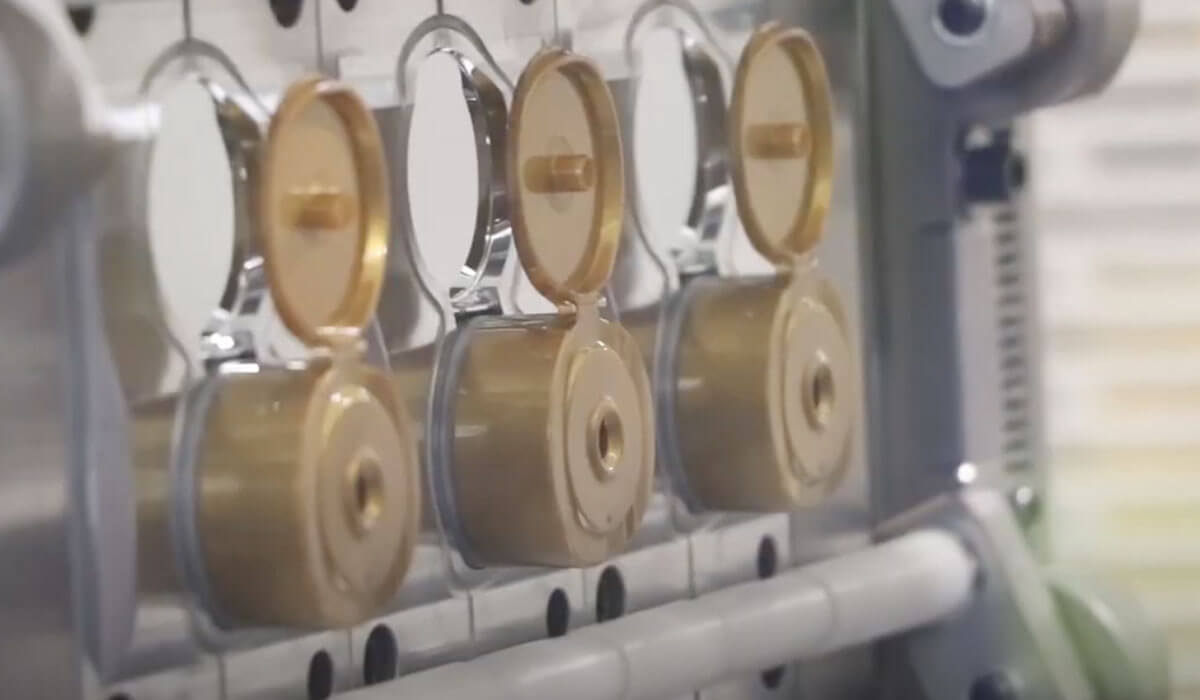
- Flip-top and cosmetic caps – appearance, hinge fatigue, gate vestige
- Medical caps – hygiene, dimensional repeatability, regulatory traceability
- Industrial oil caps – chemical resistance, thread accuracy, leak-proof radial sealing
Dimensional drift in any category leads directly to leakage, assembly failures, or unplanned downtime.
Injection molding equipment requirements
Cap production at scale requires an integrated system: machine, auxiliary equipment, and mold working in concert.
Multi-cavity molds—typically 8, 16, 32, 48, or 96 cavities—require machines that maintain uniform pressure across every cavity simultaneously. Shot size must align with total cycle demand including runners. Tie-bar spacing and platen design affect mold accessibility and cavity arrangement flexibility.
High-throughput lines integrate robotic part removal, in-mold labeling, and 100% inline inspection. The machine’s heating and cooling systems must support conformal cooling channels and hot runner control. Resin dryers and material conditioning equipment preserve feedstock quality—critical when running HDPE, LDPE, or PP with UV stabilizers and functional additives.
Water cap vs. oil cap specifications
Water caps for 18.9 L and 20 L dispensers incorporate valve mechanisms or piercing film systems compatible with automated dispensers. Molds must include precision valve seats, film-retention features, and controlled demolding sequences to protect integrated components during ejection.
Oil caps follow standards such as DIN 45, which mandates a 45 mm diameter with standardized threading for leak-proof sealing of motor oils and lubricants. The annular sealing ring generates radial compression via interference fit with the inner bottleneck surface, requiring tighter mold tolerances than many water cap applications.
The two applications drive opposite priorities: water cap molds need complex internal geometries and multi-stage cooling for thick-walled valve sections; oil cap molds prioritize thread accuracy and surface finish consistency.
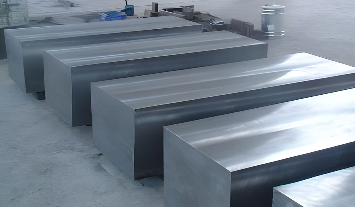
Mold material selection and surface engineering
Cap molds endure repeated compression, sliding, heating, and cooling. Steel selection must balance hardness, toughness, polishability, and corrosion resistance.
| Steel Grade | Typical Use | Key Strength |
|---|---|---|
| S136 | Food, beverage, medical cavity inserts | Corrosion resistance, mirror polish |
| H13 | High-volume cores, hot-zone inserts | Thermal fatigue, impact resistance |
| P20 | Medium-volume molds | Machinability, cost balance |
| 2316 | Medium-to-high volume cavities | Corrosion + machinability |
| 718H | Mold bases, support plates | Cost-controlled support steel |
Core and cavity inserts require higher hardness for wear resistance; support components need toughness to prevent cracking. Vacuum heat treatment reduces oxidation and improves dimensional stability.
Surface treatments
- Nickel-PTFE – reduces friction on threaded and sliding contact areas
- TiN coating – improves surface hardness on moving components
- DLC coating – superior anti-wear and low-friction for demanding sliding parts
Coating selection depends on substrate hardness, polishing quality, and edge control before deposition.
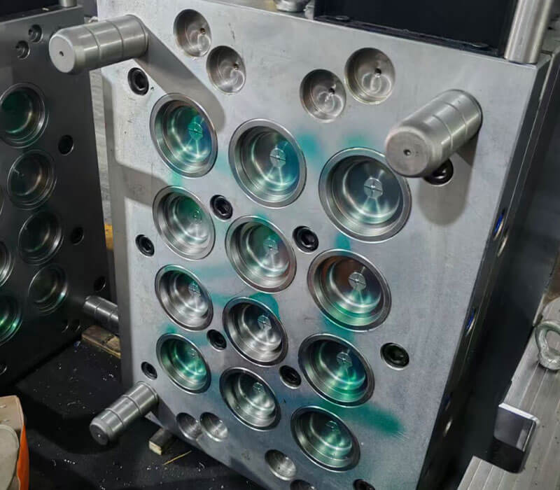
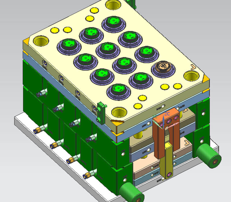
Structural particularities of multi-cavity cap molds
High-cavity molds fail first at the layout level. Typical configurations include 4×8 for 32 cavities, 6×8 for 48, 8×8 for 64, and 8×12 or 12×8 for 96. Final choice depends on cap diameter, thread core clearance, plate size, tie-bar spacing, and maintenance access.
Cavity pitch should never be reduced only to fit more cavities. Tight pitch produces weak steel sections, poor insert support, and difficult assembly. Each cavity must sit in a layout with equal mechanical loading and equal filling resistance—rheological balance requires equal flow length, equal pressure drop, and consistent shear history.
Mold base rigidity controls cavity concentricity under injection pressure. Weak support allows core shift, degrading sealing performance and thread engagement. Alignment systems should combine guide pins, precision bushings, and tapered or straight interlocks near the cavity zone.
Thermal management and cooling system specifications
Cooling channel layout should follow cap geometry, not the convenience of straight drilling. For deep cap cores, tamper-evident bands, and thin skirts, channel paths must track the internal contour with stable spacing from the molding surface.
Conformal cooling, produced by DMLS metal 3D printing, routes passages around the cap profile where conventional drilling cannot reach heat-concentration areas. It should be specified only where it solves a real thermal problem.
Core tips collect heat quickly. BeCu or high-conductivity alloy inserts can be placed at the core tip, crown zone, or sealing surface when standard steel cannot remove heat fast enough.
Cooling water must run in a turbulent state for efficient heat transfer; cap mold circuits should target a Reynolds number above 4,000. High-cavity molds need balanced cooling circuits so cap dimensions remain consistent cavity to cavity.
Hot runner system configuration
A well-configured hot runner keeps melt available at each cavity without cold runner trimming, maintaining shot balance across high-cavity tools.
Valve gate systems suit bottle caps better than open gate systems in appearance-sensitive, high-speed applications. The pin closes the gate mechanically, so vestige stays clean and stringing is easier to control. Open gates cost less initially but expose processors to drooling and wider start-up variation.
Actuation options
- Pneumatic – clean operation, fast response, standard cap molds
- Hydraulic – higher force for large caps or demanding resins; requires oil leak management
- Electric – precise pin position and sequential gating for premium or process-monitored applications
Manifold design must use smooth transitions and equal melt paths to each cavity, avoiding sharp turns or dead corners that cause shear degradation. Residence time must stay short to protect material stability. Individual tip temperature control is essential because each gate loses heat differently.
Thread processing and advanced demolding mechanisms
Threaded cap molds require controlled core rotation before ejection. Poor timing damages internal threads, scuffs sealing surfaces, and creates inconsistent release in multi-cavity tools.
- Hydraulic rack-and-pinion unscrewing – standard threads, moderate precision
- Servo-driven unscrewing – tight control of angle, speed, and torque; fits fine threads, multi-start threads, and child-resistant closures
Unscrewing pitch calculations
Pitch calculation starts from the thread lead:
- Required turns = axial release distance ÷ thread lead
- Required rotation angle = required turns × 360°
- Rack stroke = required turns × pinion pitch circumference
Synchronization with mold opening must use position-based control. Servo systems should use encoder feedback and torque limits; hydraulic systems need mechanical end stops and confirmation sensors.
Precision machining and inspection protocols
Cap mold accuracy is most critical at the sealing area, where small deviations cause leakage or assembly failures. High-volume molds may control critical inserts to ±0.005 mm where sealing performance depends on metal accuracy.
Critical control points
- Sealing ring height and roundness
- Plug seal outer diameter and taper
- Thread pitch diameter and lead-in accuracy
- Tamper-evident bridge position
- Core-to-cavity concentricity
- Parting-line mismatch at the cap skirt
High-speed CNC milling needs separate roughing, semi-finishing, and finishing strategies. EDM finishing must control discharge current, pulse timing, servo gap, flushing pressure, electrode material, and wear compensation. Polishing is functional: smooth surfaces reduce demolding resistance, but over-polishing sealing rings reduces compression force.
CMM verification should focus on functional geometry, not only nominal dimensions. Thread accuracy should be validated with optical measurement, thread gauges, and functional fit testing against the approved bottle neck. SPC should track cap weight, critical diameters, height, torque, and bridge break force by cavity number.
Assembly, trial runs, and debugging
Assembly requires alignment of cooling passages, thermal balance across the cavity layout, and correct seating of thread-processing or pneumatic ejection systems. Initial trial shots reveal whether injection pressure, hold time, cooling duration, and mold temperature align with design intent. Dimensional inconsistencies indicate machining variance; surface issues point to cooling imbalance or hot runner temperature drift. Trial production continues until consecutive shots demonstrate consistent compliance.
Injection molding process parameters
Stable cap molding starts with a narrow processing window.
| Resin | Melt Temperature | Mold Temperature |
|---|---|---|
| PP beverage caps | 200–240 °C | 20–40 °C |
| HDPE caps | 180–220 °C | 15–35 °C |
Injection pressure must fill threads, knurls, seal rings, and tamper bridges before freeze-off—without using pressure as the cure for short shots. Use a fast first stage, then switch to holding near 90–98 % fill. Holding pressure should stabilize cap weight without over-packing the top panel.
PP flows well in thin walls but responds sharply to shear and temperature. HDPE has higher shrinkage and stronger post-molding recovery, affecting thread pitch, ovality, and sealing land stability.
Common corrections
- Short shots – improve final fill, check vents
- Flash – reduce clamp pressure or holding pressure
- Oval caps – improve cooling balance
- Sink marks – adjust holding pressure and time
- Stringing – reduce gate temperature, check valve pin
- Burn marks – clean vents
- Leakage – measure sealing geometry, verify cavity-by-cavity
Manufacturing challenges and solutions
Dimensional stability depends on mold temperature control, cooling channel placement, material selection, gate location, and runner design. Cooling time is the dominant cycle-time bottleneck, especially for thick-walled or large-diameter caps. Hot runner systems and optimized cooling circuits reduce dwell time without compromising accuracy.
Material traceability matters: qualified resin suppliers, incoming inspection, and controlled storage prevent moisture absorption and contamination that degrade plastic properties.
Cost factors and efficiency
Mold cost per unit only becomes meaningful when divided by qualified cap output over the full production run. Buyers should compare mold cost, cycle time, qualified caps per shot, spare parts cost, machine tonnage, and maintenance access.
Reliable cycle gains come from removing small delays across the sequence: shorter cooling, faster ejection, smooth part drop, and stable filling. Higher cavitation reduces unit cost only when the entire system—machine, resin supply, cooling capacity, take-out, and inspection—operates at the same rhythm.
Maintenance cost starts at design review. Accessible inserts, standardized wear parts, clear cavity identification, and shot-count-based preventive maintenance reduce downtime.
Predictive maintenance and wear management
Cap molds operate under repeated thermal cycling, high injection pressures, and continuous melt contact. Wear degrades cavity surfaces and cooling channels, producing incomplete fills, air bubbles, warping, and flash.
Predictive maintenance should rely on usage-pattern analysis: monitor cavity pressure and fill times, track dimensional drift by batch, and schedule inspections based on cumulative cycle counts rather than calendar intervals. Premium tool steels and surface coatings extend intervals. Detailed performance records support refurbishment-versus-replacement decisions.
Operator competency and sustainability
Advanced mold technology underperforms when operators cannot monitor quality parameters or respond to anomalies. Training should cover SPC, ISO 9001-aligned quality monitoring, thread processing precision, and cavity pressure monitoring.
On the sustainability side, OEM buyers increasingly specify mold designs that reduce scrap and accept recycled or bio-based resins without compromising precision. Energy-efficient processing and waste-reduction protocols now factor into tooling decisions alongside ROI.
Summary
Cap mold performance depends on precision, thermal control, and demolding mechanics functioning as one integrated system. Well-processed molds reduce stoppages, stabilize daily output, protect packaging consistency, and extend tooling value. Review current tooling specifications against high-volume cap production demands, then prioritize upgrades that improve stability at the source.
Related Go4Mould resources
Continue exploring related bottle cap mold and injection molding resources:
- Injection Molding Quality Control
- Multi Cavity Molds
- Hdpe Injection Molding
- Injection Mold Cooling Design
- Aluminum Vs Steel Injection Molds
Frequently asked questions
What are the most common defects in plastic bottle caps, and how does mold design prevent them?
Leakage, inconsistent sealing edges, and dimensional drift dominate cap failures. Mold design prevents them through precise gate placement, proper cooling layout, controlled thread ejection, cavity balance, pressure hold settings, and adequate venting.
Why do multi-cavity cap molds need different cooling strategies than single-cavity molds?
Multi-cavity molds generate uneven heat distribution due to differing thermal loads and gate positions. Unbalanced cooling causes variation in thread pitch, wall thickness, and cap weight. Independent cooling circuits, thermal isolation, and per-cavity monitoring restore consistency.
How do hot runner valve gates differ from traditional sprue gates?
Valve gates maintain precise temperature control at the injection point, close mechanically for a clean vestige, eliminate sprue waste, and support faster cycle times. Traditional sprue gates suit low volumes but create more waste and often require secondary trimming.
Which defects are specific to threaded bottle caps?
Thread stripping, cross-threading, and undercut collapse occur when ejection force and thread geometry are not synchronized. Automatic unscrewing systems rotate the core during ejection to reduce shear stress on the thread flanks.
How do water caps and oil caps differ in mold cooling and gate design?
Water caps prioritize fast cooling and dispenser-compatible valve features. Oil caps prioritize chemical resistance, thread accuracy (e.g., DIN 45), and sealing geometry. A single generic process rarely fits both well.
What design rules should mold engineers enforce for bottle caps?
Engineers should control wall thickness, rib design, thread depth, draft angle, gate size, venting depth, transition radii, and sealing geometry to prevent warping, sink marks, gas traps, ejection damage, and leakage.
